CHRISTMAS AND NEW YEAR DISCOUNTS AVAILABLE!!
EMAIL US !!!! INFO@HEADLANDENGINEERING.COM.AU
Call us: +61 2 9939 1966
DAMPER DRIVE PLATE R & D MARINE
R & D Marine Damper Drive Plate
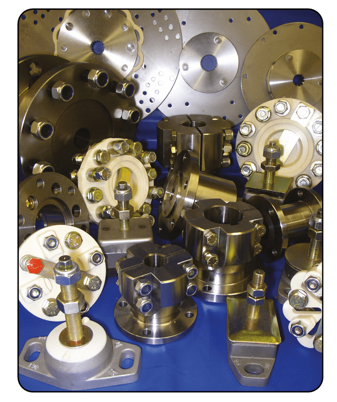
R & D Marine has developed a wide range of competitively priced Damper Drive Plates to fit most engine/gearbox combinations mostly ues in boat/ sailboat and marine applications. The R & D Damper Drive Plates reduce gear noise and allow the engine to run at lower speeds. Linear Stiffness elements for general applications and High-Deflection elements to stop gear noise and spline wear at slow speeds. All dampers are designed to be Fail-Safe and maintain the drive if the flexible element fails.The flexible elements are made from a Polyester Elastomer which has good heat qualities and is not affected by salt water, diesel and lubrication oils. Non-standard items are available for special installations, maximum back plate diameter of 533mm (21.0"). Installation is made quick and easy as the R & D Damper Drive Plate requires no machining and is ready to bolt to the flywheel. Products are available ex-stock and worldwide through our distribution network.
Below Data is required to select Damper Drive Plate:
1. Horse Power (H.P.) of Engine2. RPM/ Speed of Engine3. No. of Splines/ Teeth on the spline shaft4. Diameter of spline shaft 5. Outer diameter of Backing plate6. No. of holes on backing plate7. PCD or the distance between opposite holes on back plate8. Gear Box model no. can help in confirming fitment of the Damper Plate.9. Damper plates for BorG warner, Newage PRM, Paragon. Parsons, Self Change Gear, Technodrive, TMP, Twin Disc, Yanmar and ZF Hurth are available.
Information can be provided to us via email or phone call. * Please download brochure for technical details *
S-Series model from 23-29 kW fixed and regulated speed
The high output compression element with slow rotational speed reduces energy costs. In addition to this, the innovative design of the fail safe shaft seal, integrated oil filter and oil regulation valve, ensures external hoses are reduced to a mini-mum to guarantee the highest levels of quality and reliability are achieved.
Large surface after cooler, Optimum cooling to ensure low operating and discharge temperatures.
Tried and tested inverter concept Integrated in the electric cabinet.
Large surface after cooler, Optimum cooling to ensure low operating and discharge temperatures.
Tried and tested inverter concept Integrated in the electric cabinet.
Element Selection
Consider the following criteria when making a decision on the element design.
High Deflection (H/D)Softer than our other designs with a maximum deflection up to 30 degrees, slightly larger diameter element than other designs and can only be fitted to rotate in the standard direction of rotation (anti-clockwise looking at the flywheel). With the element facing the gearbox. Suitable for work boats with slow speed applications and pleasure boats.
Hammer Head More torsionally flexible than the loop type, usually has smaller diameter element than our other designs but still retains the ability to be mounted either way round on the flywheel and rotate in either direction. Three stage stiffness with up to 9 degrees of deflection.
Loop type General purpose robust element which can be mounted either way round on the flywheel and can rotate in either direction. Linear stiffness up to 3 degrees of deflection.
What Information We Require?
1. Manufacturer of Engine, Engine Horse Power, Engine Speed, Number of cylinders 2. Manufacturer of Gearbox, Model Number and Input Spline Details. 3. Back plate diameter, Number of holes, Size of holes, Pitch circle diameter of holes, Are they equally spaced? Does the plate fit on the face of the flywheel or locate in a register? 4. Will the element of the Drive Plate fit on the outside of the flywheel or be reversed and fit inside a flywheel recess? 5. Type of application. Pleasure or Work Boat? Does it spend long periods at low engine speeds *If an existing installation with a failed part* 6. Type and Part Number of Damper that has failed 7. What has failed. Spline or Element/Springs?
Gearbox Spline Details
Gearbox | Spline | Spline Diameter
mm inch |
| ||
71, 72, 73, 5000 | 26T 20/40 DP | 35.4 1.394 |
1000, 1500 | 22T PA 30 | 18.5 0.729 |
500 | 10T B10 x 23 x 29
DIN 5464 | 29.0 1.142 |
7000 | SAE 1.500 x 10T | 38.1 1.50 |
| ||
Delta | 17T 24/48 DP | 19.7 0.776 |
80, 120, 150 | 10T B10 x 23 x 29
DIN 5464 | 29.0 1.142 |
100, 101, 140, 160, 260 | SAE 1.000 x 10T | 25.4 1.000 |
175, 250, 265, 310 | SAE 1.125 x 10T | 28.6 1.125 |
301. 302, 401, 402, 500, 750 | 17T 16/32 DP | 28.84 1.135 |
In-Line 301, 302, 401, 402, 500, 750 | 26T 20/40 DP | 35.4 1.394 |
601, 1000 | 18T 12/24 DP | 40.5 1.595 |
1200, 1500 | 20T 12/24 DP | 44.8 1.761 |
| ||
P Series | 26T 20/40 DP | 35.4 1.394 |
| ||
SAE 1.500 x 10T | 38.1 1.50 | |
| ||
MRF 350HD | 32T 16/32 DP | 52.3 2.060 |
MRF 350 | SAE 1.625 x 10T | 41.3 1.625 |
| ||
TMC 30, 40, 50, 60 | 10T B10 x 23 x 29
DIN 5464 | 29.0 1.142 |
TM 93, 170, 260, 345
485, 545, 880 | 26T 20/40 DP | 35.4 1.394 |
| ||
1200, 1500 | 26T 20/40 DP | 35.4 1.394 |
| ||
502, 501 | 26T 20/40 DP | 35.4 1.394 |
| ||
140 Leg Old 270-280 Leg | SAE 1.000 x 10T | 25.4 1.000 |
MS3, 4, 5, HS1 Sail Drive 110
110S, New 270-280 Leg | 26T 20/40 DP | 35.4 1.394 |
120 Leg, MS 120SB, 120SC | 20T 30PA 24/48 DP | 22.6 0.89 |
| ||
Kanzaki, SD20 Sail Drive | 20T 30PA 24/48 DP | 22.6 0.89 |
| ||
HBW 35, 40, 50, 100, | 10T B10 x 23 x 29 | 29.0 1.142 |
125, 150 | DIN 5464 | |
HSW 125
HBW 250, 360 | 26T 20/40 DP | 35.4 1.394 |
HSW 450, 630, 800
IRM 220A | 26T 20/40 DP | 35.4 1.394 |
Element Details
Torque
Nm lb ft | Design | Code | Element Fixing | Rotation
(when facing fly wheel) |
HIGH DEFLECTION |
135 100 | H/D | AM | 3 x 0.375 (4.00) | Anti-Clockwise |
251 185 | H/D | AP | 4 x 0.375 (6.00) | Anti-Clockwise |
270 200 | H/D | AN | 4 x 0.375 (6.00) | Anti-Clockwise |
405 300 | H/D | AL | 4 x 0.375 (6.50) | Anti-Clockwise |
670 500 | H/D | AD | 4 x 0.500 (8.00) | Anti-Clockwise |
940 700 | H/D | AE | 4 x 0.500(10.25) | Anti-Clockwise |
HAMMER HEAD |
135 100 | Hammer | W | 3 x 0.375 (4.00) | Either |
215 160 | Hammer | D | 5 x 0.375 (5.59) | Either |
340 250 | Hammer | Y | 5 x 0.500 (5.59) | Either |
405 300 | Hammer | AJ | 3 x 0.500 (4.50) | Either |
420 310 | Hammer | L | 5 x 0.375 (5.59) | Either |
475 350 | Hammer | U | 5 x 0.500 (5.59) | Either |
745 550 | Hammer | R | 5 x 0.500 (5.59) | Either |
LOOP TYPE |
80 60 | Loop | A | 3 x 0.375 (4.00) | Either |
135 100 | Loop | B | 3 x 0.375 (4.00) | Either |
245 180 | Loop | E | 5 x 0.375 (5.59) | Either |
270 200 | Loop | F | 3 x 0.500 (4.50) | Either |
340 250 | Loop | G | 5 x 0.375 (5.59) | Either |
360 270 | Loop | H | 4 x 0.500 (4.50) | Either |
405 300 | Loop | J | 3 x 0.500 (4.50) | Either |
445 330 | Loop | K | 5 x 0.500 (5.59) | Either |
540 400 | Loop | M | 5 x 0.375 (5.59) | Either |
610 450 | Loop | N | 4 x 0.500 (4.50) | Either |
610 450 | Loop | V | 5 x 0.500 (5.59) | Either |
745 550 | Loop | P | 5 x 0.500 (5.59) | Either |
1015 750 | Loop | S | 5 x 0.500 (5.59) | Either |
1630 120 | Loop | Z | 6 x 0.625 (10.2) | Anti-Clockwise |
1630 1200 | Loop | AF | 6 x 0.625 (10.2) | Clockwise |
1901 1400 | Loop | AH | 6 x 0.625 (10.2) | Anti-Clockwise |
Damper Selection Procedure
Example 1) Ford 150 HP at 2500 RPM 6 Cylinder
2) Borg Warner Velvet Drive 72C Spline 26 teeth 20/40 DP diameter
3) Back Plate diameter 14.250, fixing holes 6 x 0.375 diameter on13.500 pcd spaced in 3 groupe of 2. No register
4) Element fits on outside of flywheel
5) Work Boat with a lot of slow speed work.
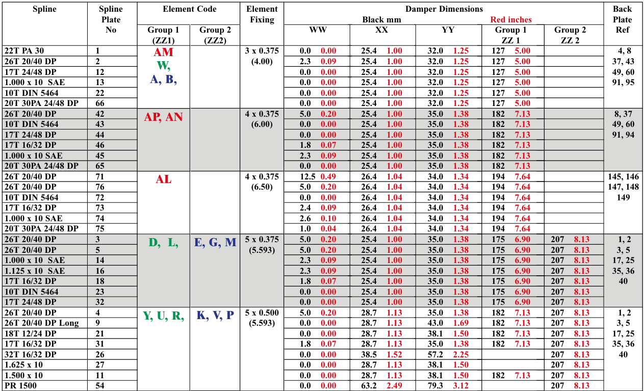
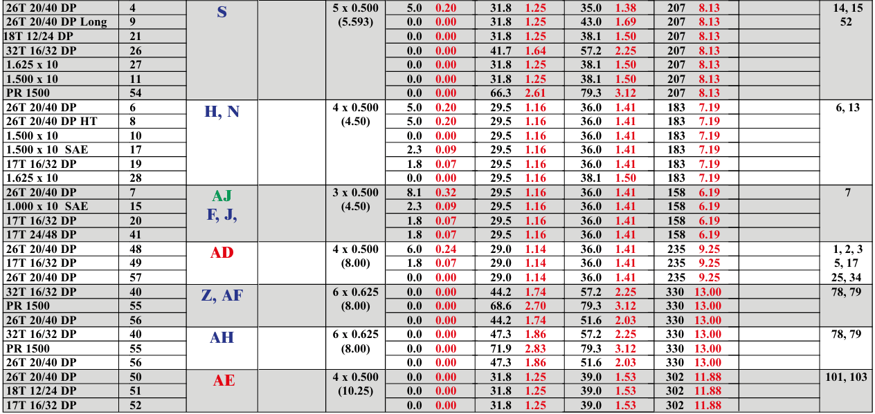
The R & D Damper comprises 3 main components, Spline plate, Element and Back plate, these 3 components are given a code which make up the finished part number.The following procedure will lead you through the selection process.
1. Select the correct power and style of element for the application.
Use the manufacturers maximum torque figure for the engine or calculate from the known data of maximum horsepower rating at what rpm. Using the example installation above we get 315 lb ft or 427 Nm
2. Select the correct Spline Plate to suit the Gearbox Input Shaft Using the example, go to the Gearbox Details to find the Borg Warner 72 has a 26 Tooth 20/40 DP input spline. In the Selection Chart below look down the Element Fixing column find 4 x 0.500 (8.00) looking across find the 26T 20/40 DP input spline, in the next column is the correct code of 48 for the spline plate. The furthest column to the right gives the reference number of the Back Plates available for this Element fixing, in this case List 7
3. Select the correct Back Plate to suit the Flywheel Using the example, go to the Back Plate List on page 4 (from the brochure). Looking down the list find the matching bolt pattern, in this case Back Plate 2
Back Plate Details
Ref | O/D
Met | O/D
Imp | Flywheel Fixing Metric | Flywheel Fixing Imperial | Remarks |
1 | 298.5 | 11.75 | 6 x 8.1 on 200 6 x 8.1 on 250 6 x 8.1 on 269.9 6 x 8.1 on 273 | 6 x .32 on 7.875 6 x .32 on 9.843 6 x .32 on 10.625 6 x .32 on 10.75 | |
2 | 362 | 14.25 | 6 x 8.1 on 200 6 x 8.1 on 210 6 x 8.1 on 263 6 x 8.1 on 269.9 6 x 8.1 on 276.3 6 x 8.1 on 289 6 x 8.1 on 295.3 6 x 8.8 on 304.8 6 x 8.1 on 314.4 6 x 9.5 on 320.7 12 x 9.5 on 343 Ford | 6 x .32 on 7.875 6 x .32 on 8.268 6 x .32 on 10.375 6 x .32 on 10.625 6 x .32 on 10.875 6 x .32 on 11.375 6 x .32 on 11.625 6 x .344 on 12.00 6 x .32 on 12.375 6 x .375 on 12.625 12 x .375 on 13.5 Ford | |
3 | 336.5 | 13.24 | 6 x 8.1 on 200 6 x 8.1 on 210 6 x 8.1 on 263 6 x 8.1 on 269.9 6 x 8.1 on 276.3 6 x 8.1 on 289 6 x 8.1 on 295.3 6 x 8.8 on 304.8 6 x 8.1 on 314.4 6 x 9.5 on 320.7 | 6 x .32 on 7.875 6 x .32 on 8.268 6 x .32 on 10.375 6 x .32 on 10.625 6 x .32 on 10.875 6 x .32 on 11.375 6 x .32 on 11.625 6 x .344 on 12.00 6 x .32 on 12.375 6 x .375 on 12.625 | |
4 | 155.45 | 6.12 | 5 x 6.35 on 142 | 5 x .25 on 5.593 | |
5 | 352.5 | 13.875 | 8 x 10.6 on 333.4 | 8 x .416 on 13.125 | SAE 11.5 |
6 | 202.6 | 7.978 | 8 x 8.1 on 181 | 8 x .32 on 7.125 | |
7 | 180.8 | 7.12 | 9 x 6.35 on 167.4 | 9 x .25 on 6.589 | |
8 | 298.5 | 11.75 | 6 x 8.1 on 200 6 x 8.1 on 250 6 x 8.1 on 269.9 6 x 8.1 on 273 | 6 x .32 on 7.875 6 x .32 on 9.843 6 x .32 on 10.625 6 x .32 on 10.75 | |
13 | 234 | 9.212 | 6 x 13.1 on 210 | 6 x .515 on 8.267 | |
14 | 352.5 | 13.875 | 8 x 10.6 on 333.4 | 8 x .416 on 13.125 | SAE 11.5 |
15 | 362 | 14.25 | 12 x 9.5 on 342.9 | 12 x .375 on 13.50 | Ford |
17 | 314.3 | 12.375 | 6 x 8.1 on 200 6 x 8.1 on 250 6 x 8.1 on 269.9 6 x 8.1 on 273 8 x 10.6 on 296 | 6 x .32 on 7.875 6 x .32 on 9.843 6 x .32 on 10.625 6 x .32 on 10.750 8 x .416 on 11.625 | SAE 10 |
25 | 287.4 | 11.312 | 6 x 9.1 on 269.96 6 x 6.3 on 269.96 | 6 x .356 on 10.625 3 x .25 on 10.625 | TAMD 40 |
34 | 466.7 | 18.375 | 8 x 13.5 on 438.15 | 8 x .53 on 17.250 | SAE 14 |
35 | 263.5 | 10.375 | 6 x 9.5 on 244.5 | 6 x .375 on 9.625 | SAE 8 |
36 | 266.7 | 10.5 | 12 x 8.1 on 222.3 6 x 8.1 on 244.5 Spaced 3 groups of 2 apart 23°59`07 12 x 8.1 on 246 12 x 8.1 on 242 | 12 x .32 on 8.750 6 x .32 on 9.625 Spaced 3 groups of 2 apart 23°59`07 12 x .32 on 9.685 12 x .32 on 9.527 | Suit Ford XLD And Mitsubishi |
37 | 266.7 | 10.5 | 12 x 8.1 on 222.3 6 x 8.1 on 244.5 Spaced 3 groups of 2 apart 23°59`07 12 x 8.1 on 246 12 x 8.1 on 242 | 12 x .32 on 8.750 6 x .32 on 9.625 Spaced 3 groups of 2 apart 23°59`07 12 x .32 on 9.685 12 x .32 on 9.527 | Suit Ford XLD And Mitsubishi |
40 | 241.3 | 9.500 | 8 x 8.5 on 222.25 | 8 x .334 on 8.750 | SAE 7.5 |
43 | 263.5 | 10.375 | 6 x 9.5 on 244.5 | 6 x .375 on 9.625 | SAE 7.5 |
49 | 241.3 | 9.500 | 8 x 8.5 on 222.25 | 8 x .334 on 8.750 | Beta |
60 | 215.9 | 8.500 | 6 x 8.1 on 200 | 6 x .32 on 7.875 | SAE 6.5 |
78 | 352.5 | 13.875 | 8 x 10.6 on 333.4 | 8 x .416 on 13.125 | SAE 11.5 |
79 | 466.7 | 18.375 | 8 x 13.5 on 438.15 | 8 x .53 on 17.250 | SAE 14 |
91 | 314.3-0.05-0.13 | 12.375-0.002-0.005 SAE 10 | 6 x 8.1 on 200 6 x 8.1 on 250 6 x 8.1 on 269.9 6 x 8.1 on 273 8 x 10.6 on 296 | 6 x .32 on 7.875 6 x .32 on 9.843 6 x .32 on 10.625 6 x .32 on 10.750 8 x .416 on 11.625 | SAE 10 |
94 | 287.4 | 11.312 | 6 x 9.1 on 269.96 6 x 6.3 on 269.96 | 6 x .356 on 10.625 3 x .25 on 10.625 | Trans Auto TAMD 40 |
95 | 235 | 9.250 | 6 x 8.1 on 222.25 | 6 x .32 on 8.750 | BETA |
101 | 352.5 | 13.875 | 8 x 10.6 on 333.4 | 8 x .416 on 13.125 | SAE 11.5 |
103 | 466.7 | 18.375 | 8 x 13.5 on 438.15 | 8 x .53 on 17.250 | SAE 14 |
145 | 215.9 | 8.500 | 6 x 8.1 on 200 | 6 x .32 on 7.875 | SAE 6.5 |
146 | 241.3 | 9.500 | 8 x 8.5 on 222.25 | 8 x .334 on 8.750 | SAE 7.5 |
147 | 263.5 | 10.375 | 6 x 9.5 on 244.5 | 6 x .375 on 9.625 | SAE 8 |
148 | 314.3 | 12.375 | 8 x 10.6 on 296 | 8 x .416 on 11.625 | SAE 10 |
149 | 352.5 | 13.875 | 8 x 10.6 on 333.4 | 8 x .416 on 13.125 | SAE 11.5 |
The above table shows some of the 160 standard back-plates we produce.R & D Marine can manufacture one off specials up to 533mm [21.0”] Ø. Please contact Headland Engineering for your requirement.
Details below
FILL CONTACT FORM FOR MORE INFORMATION!!!
- Designs are subject to constant review and mprovement therefore we reserve the right to amend any dimension or detail specified or illustrated in this publication without notice and without incurring any obligation to provide such modification to products previously delivered.
It all starts with one quick, no-obligation conversation!